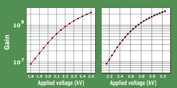
Measurement of the Gain Characteristic
The gain of a channel electron multiplier is dependent on the applied voltage. Gain increases continuously with applied voltage until saturation is reached. One finds that the gain of a CEM cannot be increased above several 10e8 because of the space charge limitation within the electron cloud. As it approaches the CEM output, the space charge causes self-repulsion and drives the secondary electrons back to the wall before they have gained sufficient energy from the electric field to produce secondary electrons. Thus, the amplitude of the output pulse reaches a certain level at several 10e8 and will increase no further. The beginning space charge limitation and therefore non-linearity of the gain can be seen at a value of about 5 x 10e7 in the gain characteristic.
For the final test sheet, which is delivered with every CEM, we measure the gain characteristic after the clean-up phase, so that the detector has already been in operation for several hours and the gain is in the stable plateau of the burn-in curve. This ensures that the gain characteristics in the clean-up phase do not show values that are too high and the individual CEMs are comparable to each other. Knowledge of the gain characteristic is also necessary when selecting individual detectors for CEM arrays.
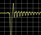
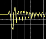
Fig. 7 Typical gain characteristics of standard (left) and EDR (right) type CEMs |
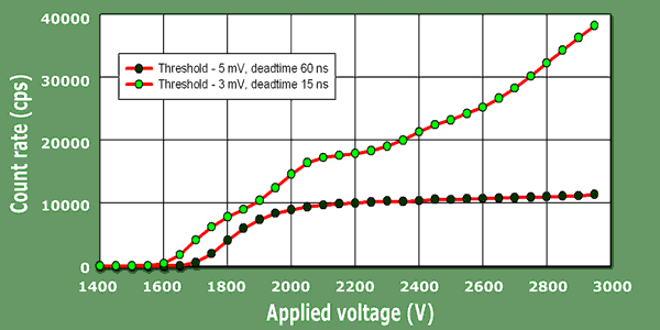
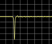
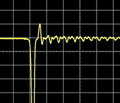
| Fig. 9 Measurement of the High voltage vs. Counts plot with correct (- 5mV) and incorrect (- 3mV) threshold and different dead times using the MEASAR |
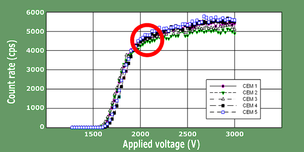
Determining the optimal working point
|
Very important for the experimenter is the determination of the optimal working point at which the CEM should be operated. The operation voltage should be as low as possible in order to extend the lifetime of the CEM. An increase in the applied voltage beyond the optimal working point only leads to the increase in the accumulated load per output pulse, without any advantage to the measuring accuracy.
Fig. 8 Determining the optimal working point with constant radiation source |
The optimal working point is determined by the measuring curve Counts vs. Applied Voltage, in which the measured count rate in a given time interval is plotted against the applied voltage. This measurement can easily be conducted with many vastly constant radiation sources (ion gauge, mass spectrometer etc.). It must be made sure, however, that the polarity of the CEM funnel opening does not present any potential barriere for the parcticles to be detected, so that the curve drops again with increasing operating voltage. Fig. 8 shows the Counts vs. Applied Voltage curves of the CEM type KBL210 that was recorded with the MEASAR measuring system. The radiation source was an isotope mass spectrometer. The optimal working point lies in the falling point of the curve (circle), the applied voltage for a new CEM is between 2.1 and 2.2 kV.
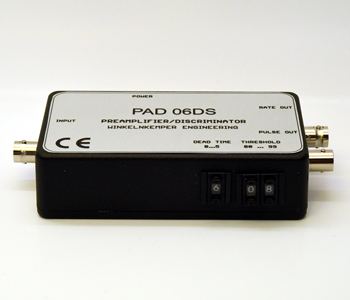
Setting the discriminator threshold and deadtime |
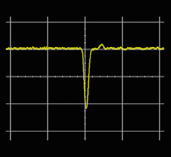
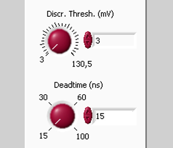
The adjustable discriminator threshold of the pre-amplifier is the limit in mV, at which the input signal from the CEM anode is just still changed into a positive count signal. Pulses that are lower are suppressed and therefore not counted. If the discriminator threshold is correctly set, neither interference pulses are counted nor is there a loss of count at higher count rates. A typical value for a correctly placed discriminator threshold is - 5 mV. At this threshold, the smaller pulses from electronic noise are not detected and at very high count rates, at which the gain of the channel electron multipliers sinks, the count loss is acceptable.
Even the dead time of the pre-amplifier should not be selected too large or too small. In the burn-in phase of a CEM, multiple pulses could arise that can distort measurements. Here it is recommended to use a dead time of 100 ns. Afterwards the dead time can be set to a value of 30 ns or 60 ns, depending upon if the measurement should be conducted at a very high counting rate or not. The correct setting of the dead time and discriminator threshold can be checked as long as a constant radiation source is availabe.
For this purpose, the applied voltage of the CEM at constant count rate (that is not too high), the applied voltage of the CEM is increased in increments. At approximately 1600 V, the signal sets in that should evenly increase with the high voltage until it drops down at the working point and swings to a plateau with a slight increase. If other structures can be seen, then the discriminator threshold and/or the dead time must be corrected.
|