Burn-in procedure
All CEMs are fully tested prior to shipment. The measurements of the burn-in phase and of the gain characteristic are documented in a final test sheet.
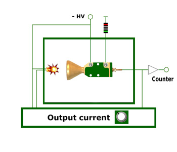
For these measurements, the CEM is operated in a feedback system as illustrated schematically in Fig. 1. A hot filament, which emits thermal electrons, is placed in front of the CEM opening. The output current has a preselected value, i.e. 1 µA. The heating current of the filament automatically readjusts when deviation from the preselected value occurs. The output current IA is the product of the number n of the output pulses per second, the momentary gain G of the CEM and the elementary charge e
Output current IA = G · n · e
The number n of the output pulses per second that are necessary to produce the preselected output current IA is measured. The gain G is the quotient of the output current to the number of output pulses per second. The number of output pulses is measured at certain time intervals (e.g. for 10 seconds every minute) and G is calculated for this interval.
The values are displayed in the gain vs. accumulated charge plot.
Gain G = IA / n · e
Fig. 5 Typical burn-in plot for a standard type channel electron multiplier
The burn-in phase is characterized by a decrease in gain after an initial high value, followed by a stable plateau of gain at the beginning of the CEM lifetime. The initial gain drop that is common to all multipliers after they have been exposed to air is due to a loosely-bound gas cover at the surface of the channel. It reduces the work function of the glass, so that the secondary electron emission is higher than for a gas-free surface. Under the onset of particle bombardment, this gas is desorbed. This initial rapid drop in gain, which all multipliers exhibit after exposure to air, has been called "clean-up phase". After this rapid decrease, the gain levels at a plateau value. The operational characteristics of the CEMs then remain stable until about 10e10 counts.
| ! |
Please note that a CEM always goes through the burn-in phase from the beginning if it was exposed to the ambient air. This must be considered when setting the discriminator threshold. |
The burn-in curve of a CEM that was exposed to the ambient air for a longer period of time has a slightly different characteristic run. After the rapid decrease of gain, the burn-in curve goes through a minimum in order to then slowly swing to the stable plateau. The experimenter can easily notice this effect due to a rapid decrease of the measured counting rate if the discriminator threshold is set too high at the beginning of the measurement.
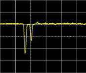
Multiple pulses during the clean-up phase |
During the clean-up phase, an increased number of multiple pulses may appear, because returning ions in the funnel create secondary electrons again that trigger a second or third electron avalanche. While the change in gain in the burn-in area is not noticed, as long as the discriminator threshold is correctly placed, the multiple pulses distort quantitative measurements if the dead time of the pre-amplifier is set for under 100 ns. Measured quantum yields during the burn-in phase of over 100 % show that pulses were also counted that originated within the detector. After the stable plateau of the gain has been reached, the number of these multiple pulses becomes insignificant. For quantitative measurements with higher accuracy, it is recommended to operate the channel electron multipler before the experiment for some time.
| |
User Report |
|
|
|
| |
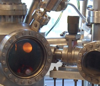
Metastable Impact Electron Spectroscopy |
|
Courtesy of F. Bebensee, F. Voigts |
|
and W. Maus-Friedrichs |
Technical University Clausthal |
| |
|
|
|
|
| |
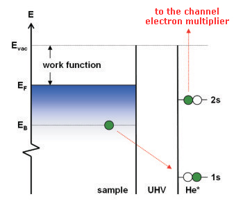
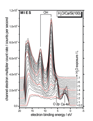
The adjoining figure shows a set of electron spectra that were recorded using Metastable Impact Electron Spectroscopy (MIES). The channel electron multiplier count rate is plotted against the binding energy of the collected electrons with respect to the Fermi level at 0 eV. MIES uses metastable He* to exite electron emission from a surface and displays the surface density of states of the valence band region of the sample.
The shown figure depicts the reaction of a Calcium sample prepared in an ultrahigh vacuum with water. The progress of the experiment can be tracked on the right side with water exposure indicated by the arrow. The reaction begins with the total dissociation of impinging water molecules in front of the surface. The subsequent chemisorption of oxygen atoms on the surface can be deduced from the evolution of the peak denoted O 2p.
|
|
 |
|
| |
|
|
|
|
| |
Simultaneously, the surface loses its metallic character, as can be seen from the diminshment of the Ca 4s metallic state. As soon as the surface becomes covered with oxygen, fractional dissociation of the impinging water molecules takes place resulting in the formation of surface OH groups which |
|
are very sensitively deteced by MIES. The double feature denoted OH in the figure corresponds to their 1π
and 3σ
molecular orbitals. As the water exposure continues, the surface is completely covered with surface OH groups. The chemisorbed oxygen is completeley consumed in the reaction.
|
|
| |
|
|
|
|
|