Electrical Connections
For the operation of a CEM a potential difference between the CEM input and the CEM output must be applied. In principle, this difference must increase positively from the CEM input to the anode so that the anode is on the highest positive potential. A potential difference of 100 V between the output end of the CEM and the anode accelerates the electron cloud out of the CEM toward the anode resulting in maximum gain and narrow pulse height distribution.
| ! |
The bias voltage between the CEM output and the anode may not significantly exceed 100 V. The ceramic anode support cannot sustain voltages over 200 V, which could lead to an instable operation of the CEM. |
Using a resistor to create a voltage difference of 100 V
Depending on the polarity of the incident particles, a positive high voltage must be applied to the output end of the CEM or a negative high voltage must be applied to the CEM input. It is important not to create a potential barrier to the charged incident particles which could then hinder their penetration into the CEM funnel. These considerations are of course not applicable to the detection of UV and X-ray photons. The simplest way to create a potential difference between the end of the CEM and the anode is by using a resistor of about 10 MOhm for standard type CEMs with a typical wall resistance of 250 MOhm and 3 MOhm for the EDR type CEMs that is in series with the CEM. Fig. 3 shows an example for the use of positive high voltage. Here a capacitor must be used in the signal.
| ! |
Please make sure that the resistance R has a value of approximately 1/25 of the wall resistance of the CEM in order to create a bias voltage of about 100 V between the CEM output and the anode.
|
Using a Z-diode to create a voltage difference of 100 V
In order to create a stable voltage difference between the CEM output and the anode, it is much easier to use a Z-diode. The level of the bias voltage no longer depends on the wall resistance of the detector that may change over time and also during operation due to warming. Is is also irrelevant if a standard or an EDR type is used. A suitable Z-diode is, for example, the type BZX85C120 from VISHAY Semiconductors. It is only important that the diode is correctly implemented.
|
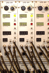
Fig. 7 The control units we use to measure the CEM performance were built by WMT Elektronik GmbH to measure the
|
| |
|
Burn-in procedure |
| |
|
Starting voltage |
| |
|
Gain characteristic after the burn-in |
| |
|
Dark count rate |
| |
|
Pulse height distribution |
| |
|
Gain vs Count rate plot |
| |
|
Count rate vs Applied voltage plot |
The excellent experience we made over many years with this control units led to the development of the measurement system MEASAR to enable the customer to operate channel electron multipliers with a stand-alone device. |
Use of a CEM Series KBL in the closed mode (2 electrical connections)
There are not always as many vacuum feedthroughs available as required for the use of a resistor or a Z-diode. This is mainly the case for older mass spectrometers in which channel electron multipliers are used that are closed at the end (closed mode). An essential disadvantage of the closed CEMs is that they do not show the same gain under the same conditions as the openly operated CEMs do, since the space charge effects at the end of the channel are not equalized by a bias voltage. The lifetime of the CEMs is therefore greatly reduced because less leeway remains for a successive increase of the applied voltage after the gain degradation occured.
|
|
|
| |
|
|
Fig. 8 Comparison of the amplification of a standard type CEM in the open and closed mode at a medium counting rate. The constant anode current was 1 x 10e-6 A |
|
|
Fig. 9 Comparison of the amplification of a standard type CEM in the open and closed mode at a very high counting rate. The constant anode current was 1 x 10e-5 A |
|
| |
|
|
|
|
CEMs as part of an electro-optical system
Often a CEM is part of an electro-optical system consisting of slits, ring electrodes or grids. The influence of their electrical fields must also be taken into account. In addition to such desired effects as the repelling of secondary particles by means of a grid electrode or the increase of the effective area of the CEM by a ring electrode which may be necessary in order to prevent the loss of secondary electrons produced on the funnel edge unwanted effects may occur as well. If the distance between the electro-optical elements and the CEM is too small, the applied voltage can lead to field electron emission and unwanted pulses. A ground potential in front of the CEM that operates with negative high voltage generates an acceleration voltage onto the secondary electrons in the CEM funnel and can reduce gain significantly.
Resistors, capacitors and Z-diodes inside or outside the vacuum chamber?
Unfortunately, there are no electronic components available on the market that are highly suitable for vacuums that can be heated up to 200°C. Exceptions are components in surface-mounted device (SMD) technology. We therefore suggest installing the electronic components as closely as possible to the voltage feedthroughs of the vacuum flange if they are to be operated at a very high count rate. The length of the signal cable is uncritical (up to some meters) as long as the amplifier's input resistance is matched to the characteristic impedance of the cable (usually 50 Ohm). This is the case for all PAD offered. For positive high voltage the coupling capacitor should be located directly at the vacuum flange. The signal cable must not carry high voltage, because a strong electric field in the cable creates dark counts.
|